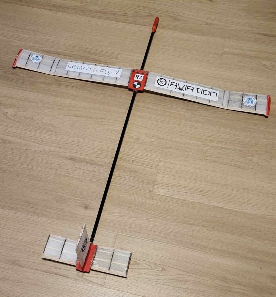
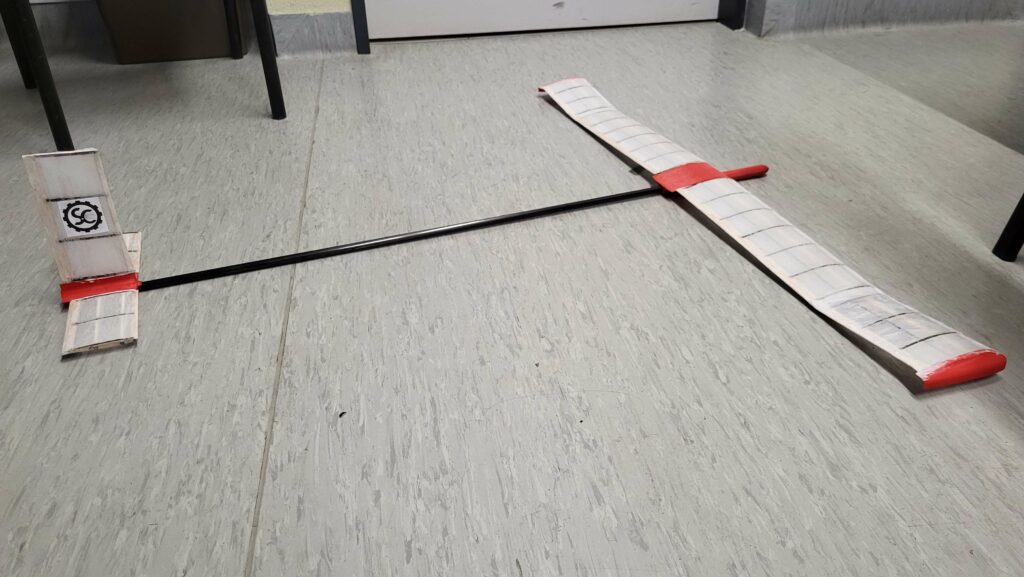
The project’s goal is to create a small hand-thrown glider in order to participate in the Learn&Fly contest, focused on developing engineering and construction instrests and competences of young people. It’s a four-person-team project, that the members of our Club have undertaken to test their current competences in construction-focused assignments, along with once again taking up the challenges concerning engineering design.
Development of the project
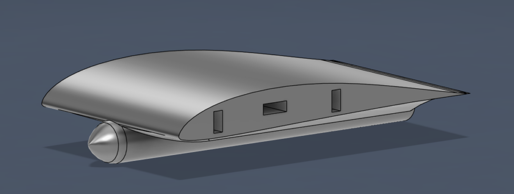
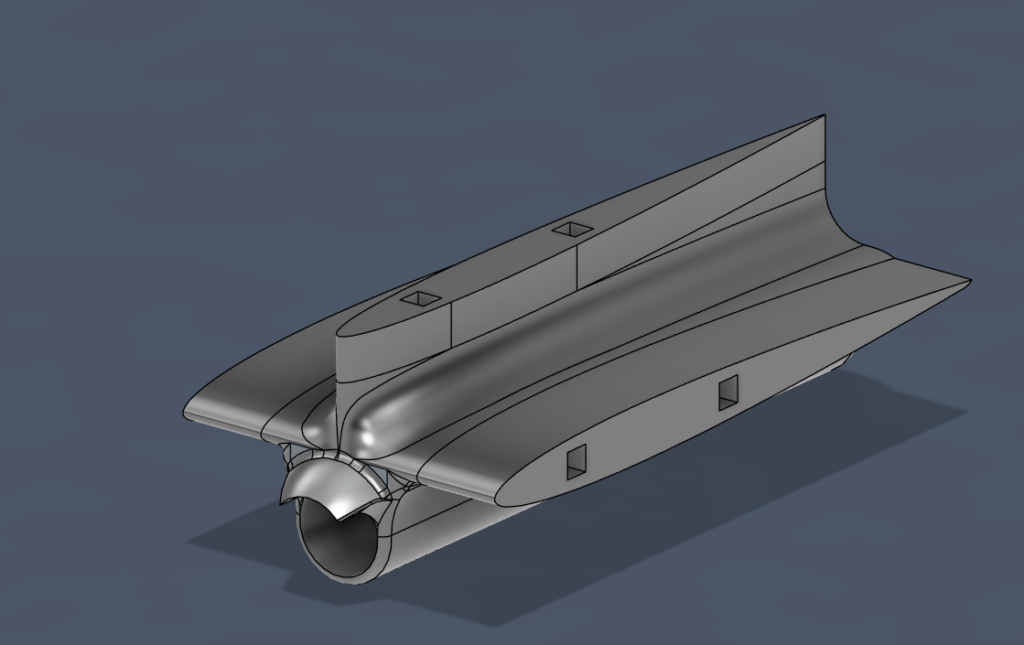
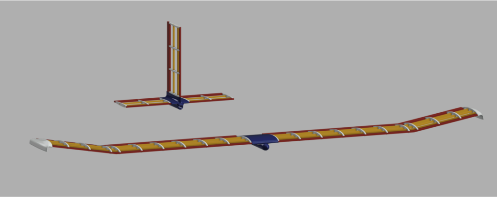
We began work on the glider by creating a 3D model. After creating several versions of the design, we finally decided on the following model of the glider:
– divided into easily removable segments.
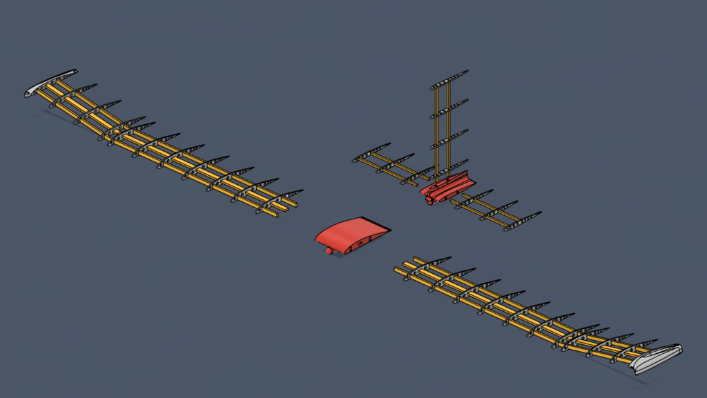
– wing and stabilizer mounts printed on a 3D printer and connected by a carbon fiber tube – the printing will ensure high strength, lightness, as well as low cost of making the components.
– carbon fiber to connect the mounts – still a lightweight but strong material, to make the key structural element, the core of the entire glider.
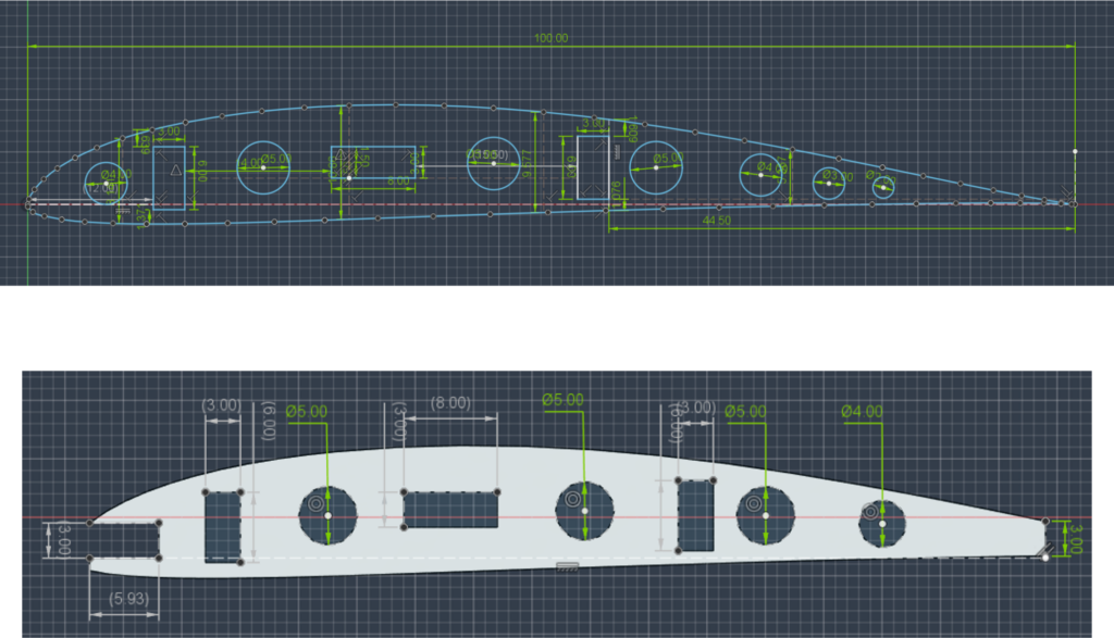
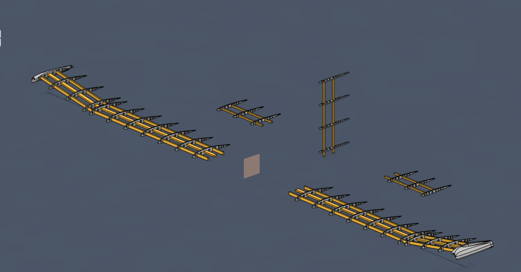
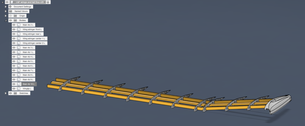
– the wings made almost entirely of balsa wood, along with the stringers and ribs, cut by CNC laser from a sheet of balsa wood. By cutting round holes in the ribs, the glider’s weight will be further reduced.
– the wing covering made of a material similar in structure to shrink film, providing low weight, relatively high strength, but most importantly, adhering well to the ribbing of the wings.
In addition, we want to perform an aerodynamic simulation of the designed components to make sure that the prototype in its current state will be able to achieve the desired results.
Design: gallery
Project description
Wings
The wings have a rib-and-girder design with an S4310 profile, bent 10 degrees upward at a distance of 31cm from the fuselage. To allow the wings to be sheathed, they have a slip and chute edge made of balsa. The wings have 3 main spars, two of which are one-piece, while one of them, the middle one, is divided into two parts. One wing is 488 mm long. Each wing has 10 ribs and is finished with a winglet. These elements allow us to increase the efficiency of the wing and increase the horizontal stability of the aircraft.
Ballasts
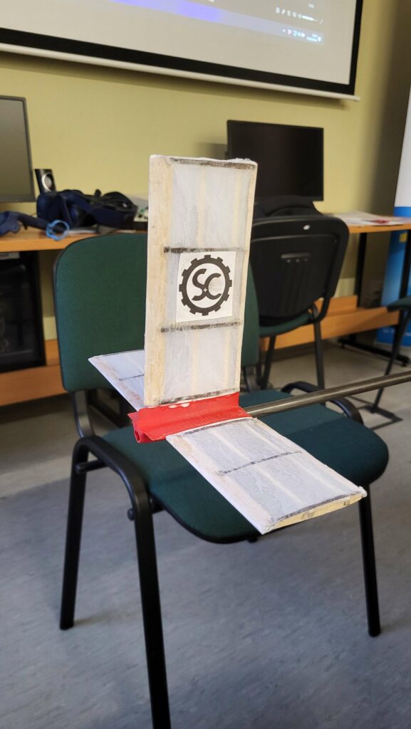
Ballasts also have a rib-and-girder design, one difference is that ballasts have only 2 girders instead of 3. They have a chute and leading edge similar to those used in wings. The horizontal stabilizers have 3 ribs per side, while the vertical stabilizer has 4 ribs.
Wing and aileron mounts and the fuselage
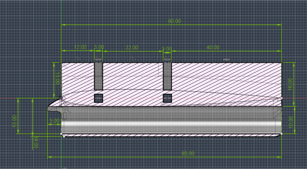
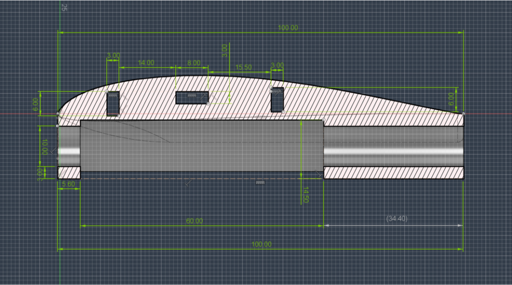
The front wing mount is made by 3D printing, which gives us optimal strength and weight. In addition, it accommodates a weight baffle and additional weighting for balancing the aircraft. 3D printing provides us with the ability to make complex geometry to minimize aerodynamic drag.
The rear element to which the horizontal as well as vertical stabilizers are attached is also made using 3D printing technology.
The fuselage is made of carbon fiber tubing, which gives us strength and relatively low weight. The only drawback of this solution is excessive flexibility, but we solved this problem.
Construction process and final model
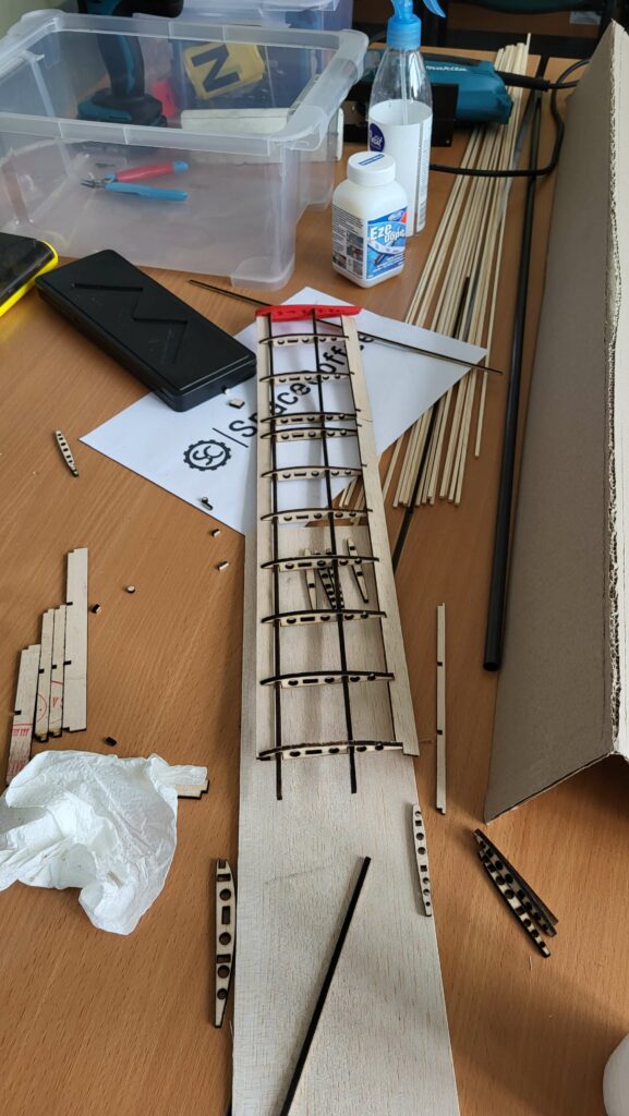
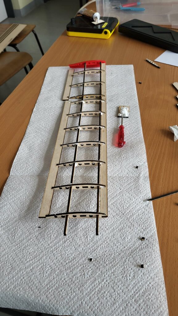
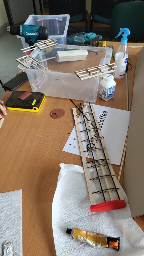
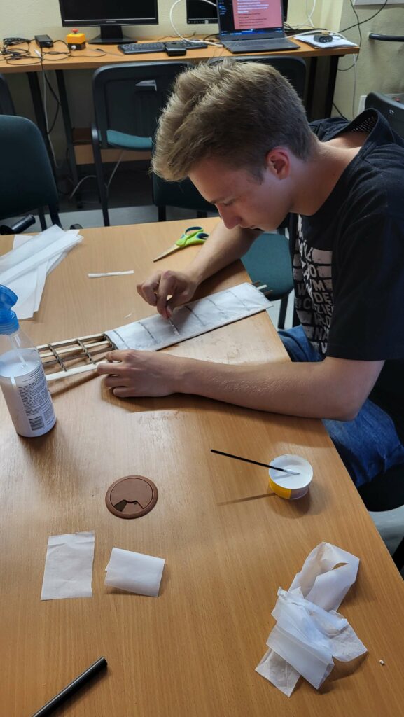
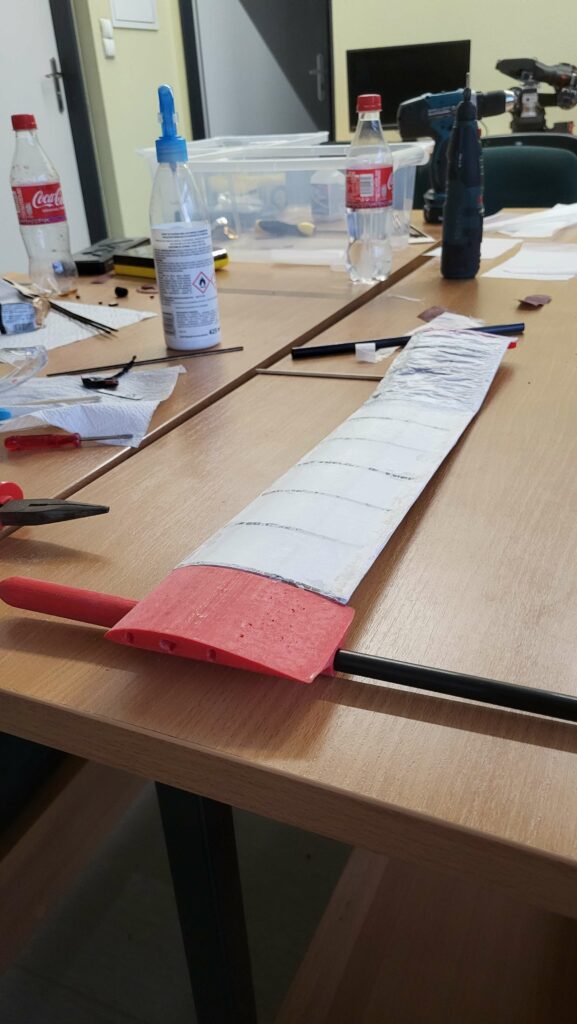
After cutting out the wing elements, we pre-sanded them and verified that the parts fit, then assembled the wings, ensured that everything was straight and started the gluing process. After waiting for the glue to dry, we got down to the sheathing. First we cut the paper to size and glued it down. After the glue dried, we used astringent varnish to smooth out the plating.
We made the stabilizers in the same way as the wings, i.e., after cutting out the parts, we sanded them with sandpaper, checked their fit, then glued them together and covered them with paper that was pulled off with varnish.
We printed the printed parts from PLA, and because of their complex geometry, they were printed with support material, so we had to remove this support material and grind the parts after printing.
Contruction: gallery
Model: gallery
