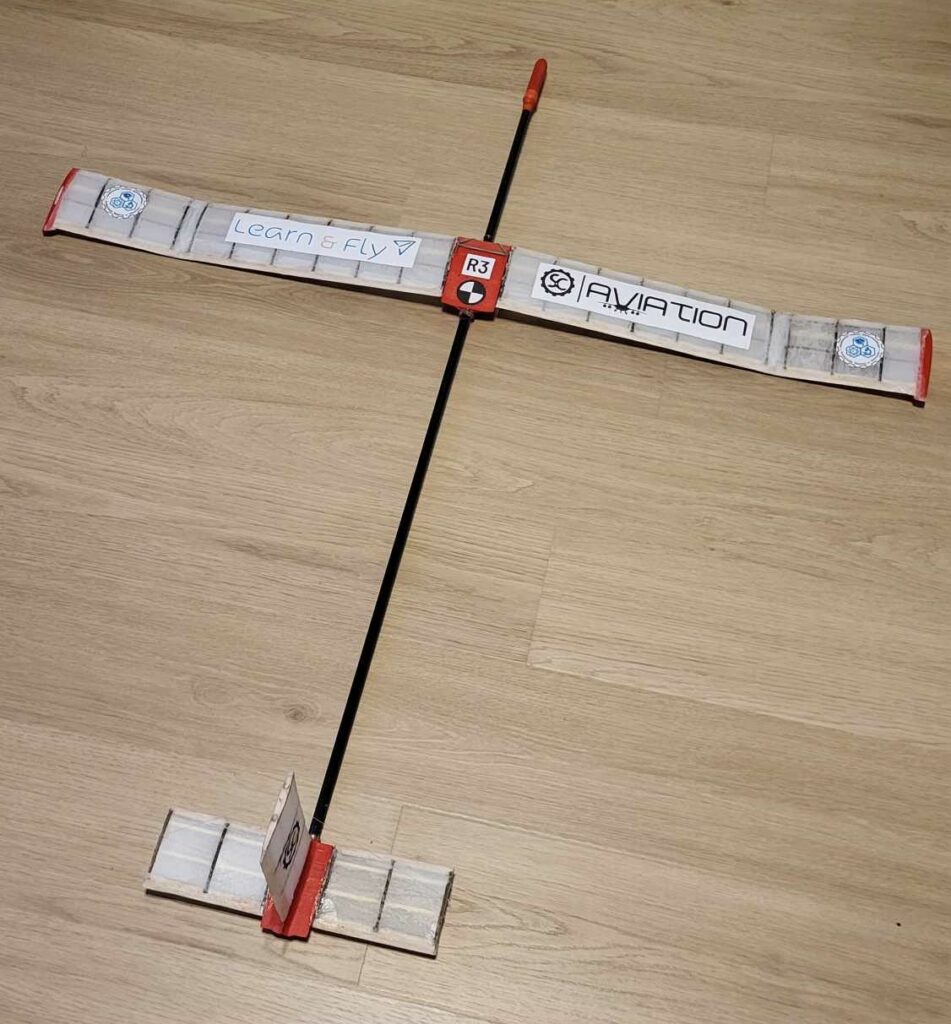
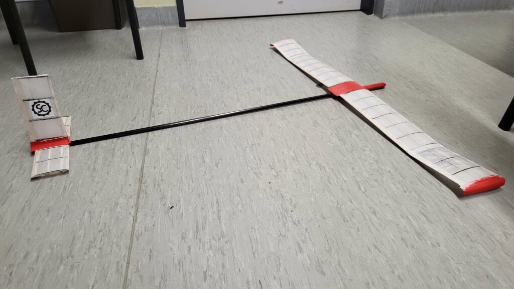
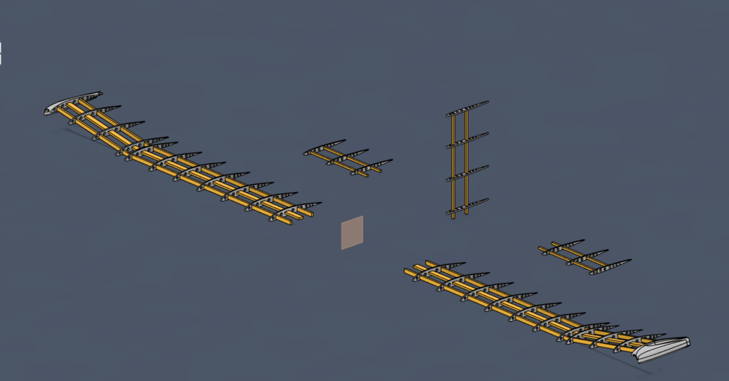
Celem projektu jest stworzenie małego, ręcznie rzucanego szybowca, który weźmie udział w konkursie Learn&Fly, ukierunkowanym na rozwijanie zainteresowań i kompetencji inżynieryjno-konstrukcyjnych młodzieży. Jest to czteroosobowy projekt zespołowy, którego członkowie naszego Koła podjęli się, aby sprawdzić swoje obecne kompetencje w zadaniach konstrukcyjnych, a także po raz kolejny podjąć wyzwania związane z projektowaniem inżynierskim.
Rozwój projektu
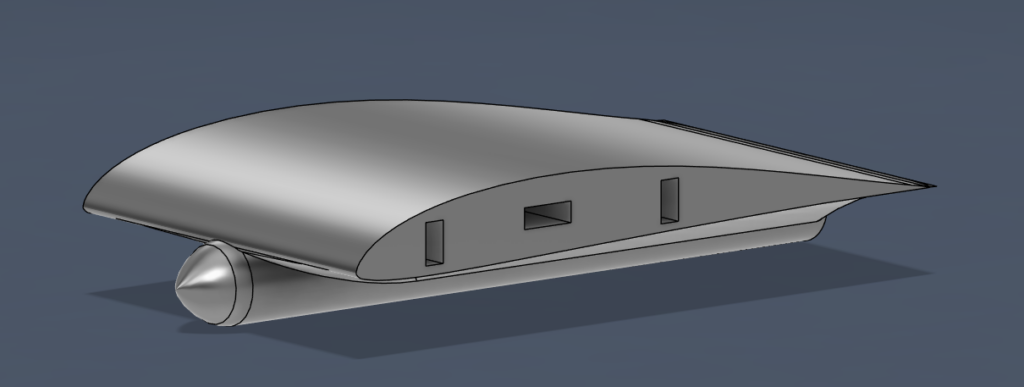
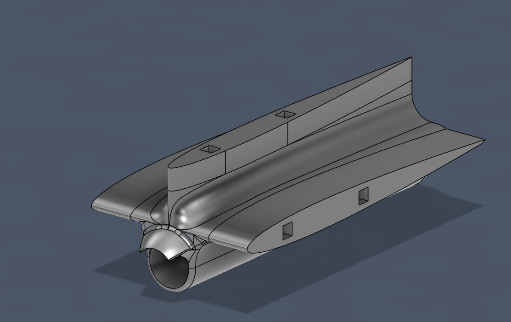
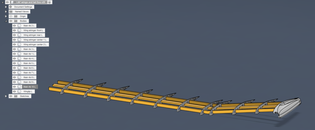
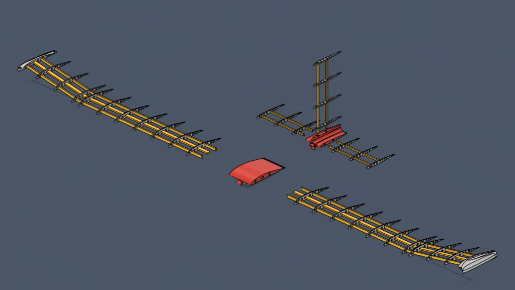
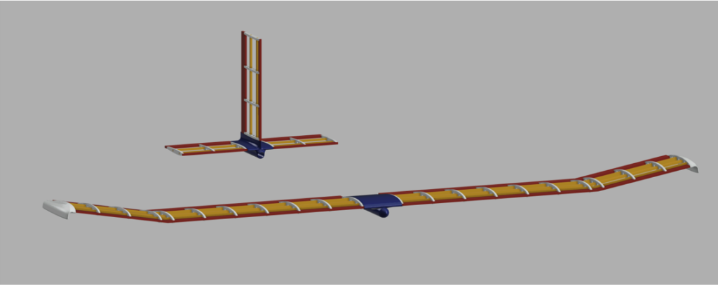
Prace nad szybowcem rozpoczęliśmy od stworzenia modelu 3D. Po opracowaniu kilku wersji, ostatecznie zdecydowaliśmy się na poniższy model szybowca:
– podzielony na łatwe do wymiany segmenty.
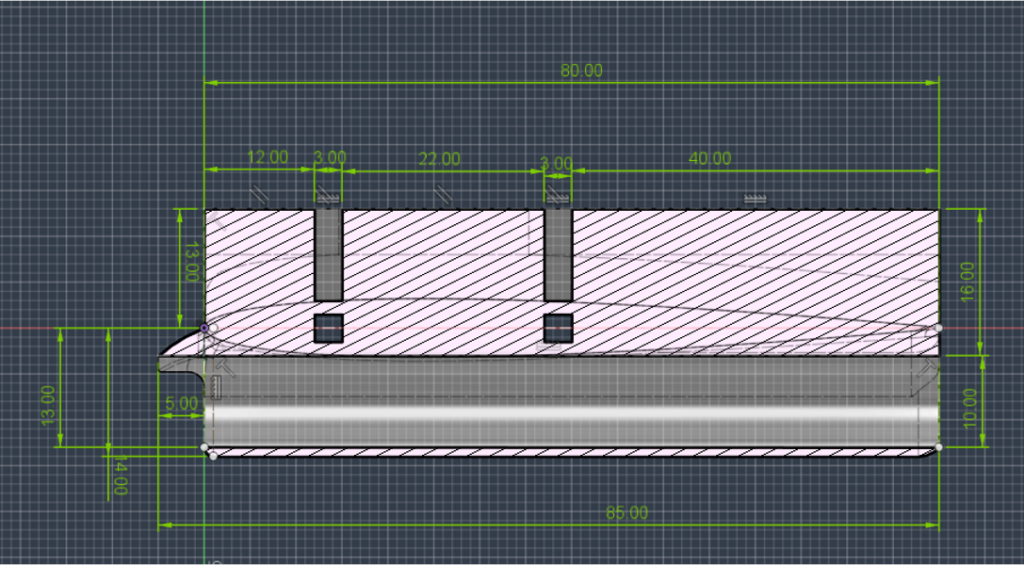
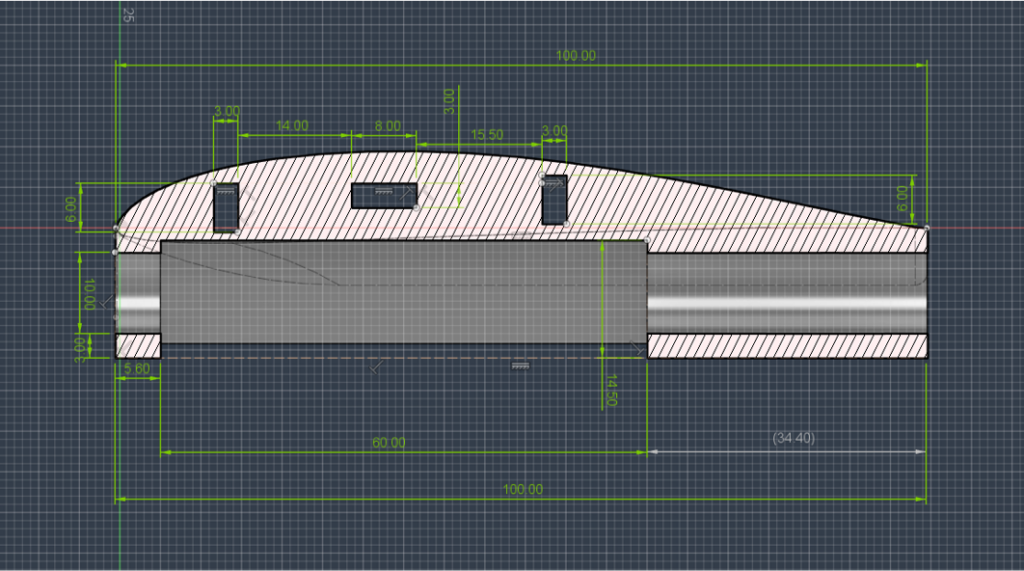
– mocowania skrzydeł i statecznika wydrukowane na drukarce 3D i połączone rurką z włókna węglowego — druk zapewni wysoką wytrzymałość, lekkość, a także niski koszt wykonania komponentów.
– włókno węglowe do łączenia mocowań — wciąż lekki, ale wytrzymały materiał, aby stworzyć kluczowy element konstrukcyjny, rdzeń całego szybowca.
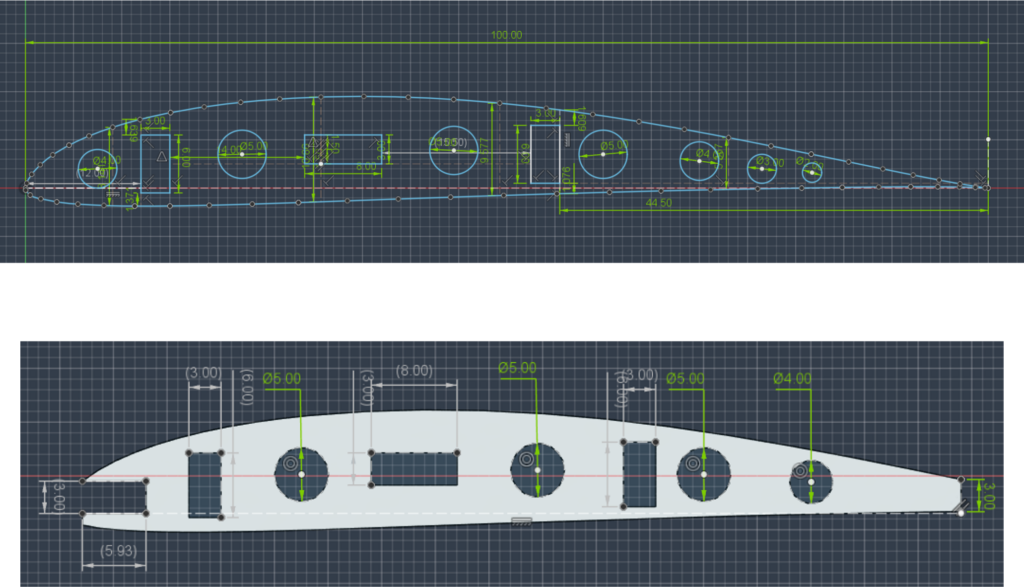
– skrzydła wykonane prawie w całości z drewna balsy, wraz z podłużnicami i żebrami, wycięte laserem CNC z arkusza tego drewna. Wycinając okrągłe otwory w żebrach, waga szybowca zostanie dodatkowo zmniejszona.
– pokrycie skrzydeł wykonane z materiału o strukturze podobnej do folii termokurczliwej, zapewniające niską wagę, stosunkowo wysoką wytrzymałość, ale co najważniejsze, dobrze przylegające do ożebrowania skrzydeł.
Ponadto chcemy przeprowadzić symulację aerodynamiczną zaprojektowanych komponentów, aby upewnić się, że prototyp w obecnym stanie będzie w stanie osiągnąć pożądane rezultaty.
Galeria: projekt
Project description
Skrzydła
The wings have a rib-and-girder design with an S4310 profile, bent 10 degrees upward at a distance of 31cm from the fuselage. To allow the wings to be sheathed, they have a slip and chute edge made of balsa. The wings have 3 main spars, two of which are one-piece, while one of them, the middle one, is divided into two parts. One wing is 488 mm long. Each wing has 10 ribs and is finished with a winglet. These elements allow us to increase the efficiency of the wing and increase the horizontal stability of the aircraft.
Ballasts
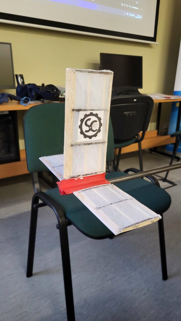
Ballasts also have a rib-and-girder design, one difference is that ballasts have only 2 girders instead of 3. They have a chute and leading edge similar to those used in wings. The horizontal stabilizers have 3 ribs per side, while the vertical stabilizer has 4 ribs.
Wing and aileron mounts and the fuselage
The front wing mount is made by 3D printing, which gives us optimal strength and weight. In addition, it accommodates a weight baffle and additional weighting for balancing the aircraft. 3D printing provides us with the ability to make complex geometry to minimize aerodynamic drag.
The rear element to which the horizontal as well as vertical stabilizers are attached is also made using 3D printing technology.
The fuselage is made of carbon fiber tubing, which gives us strength and relatively low weight. The only drawback of this solution is excessive flexibility, but we solved this problem.
Construction process and final model
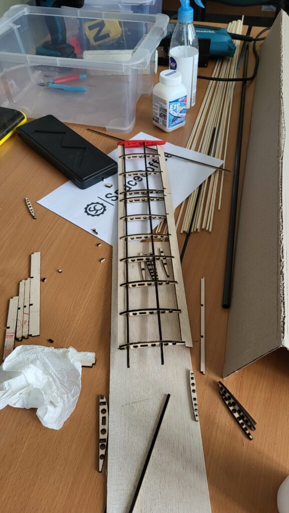
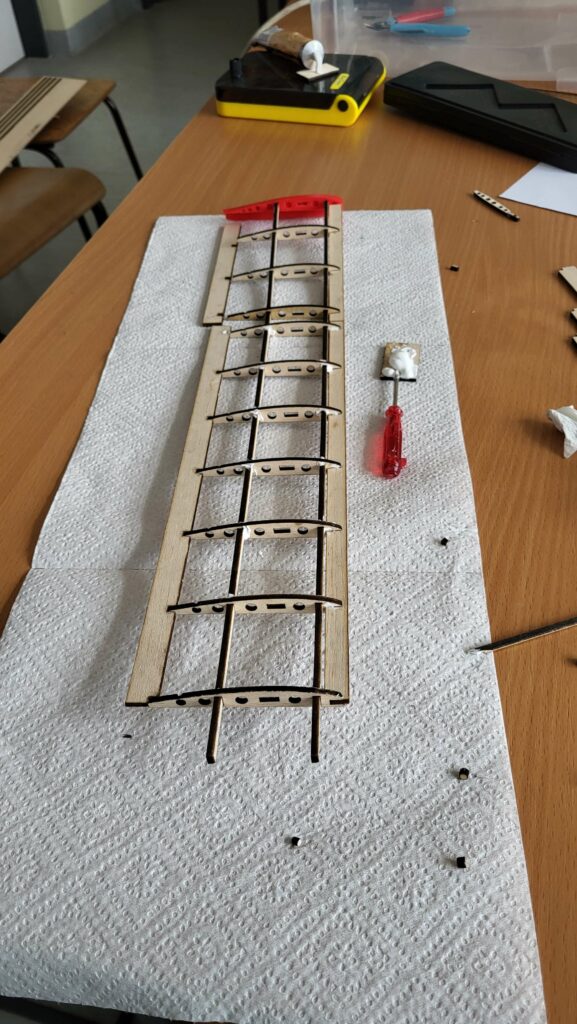
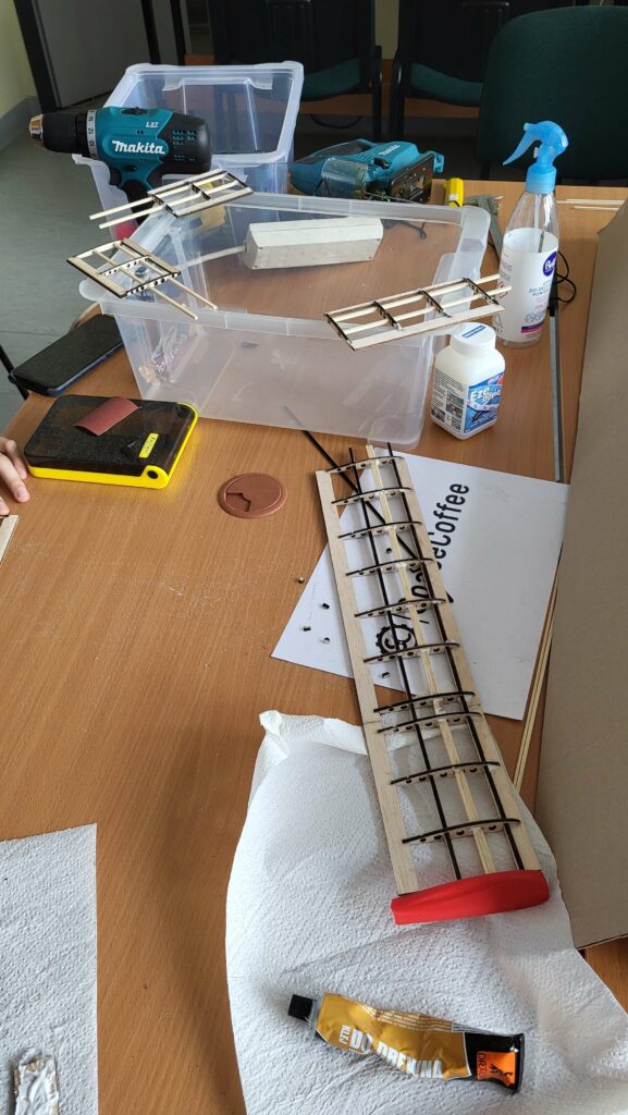
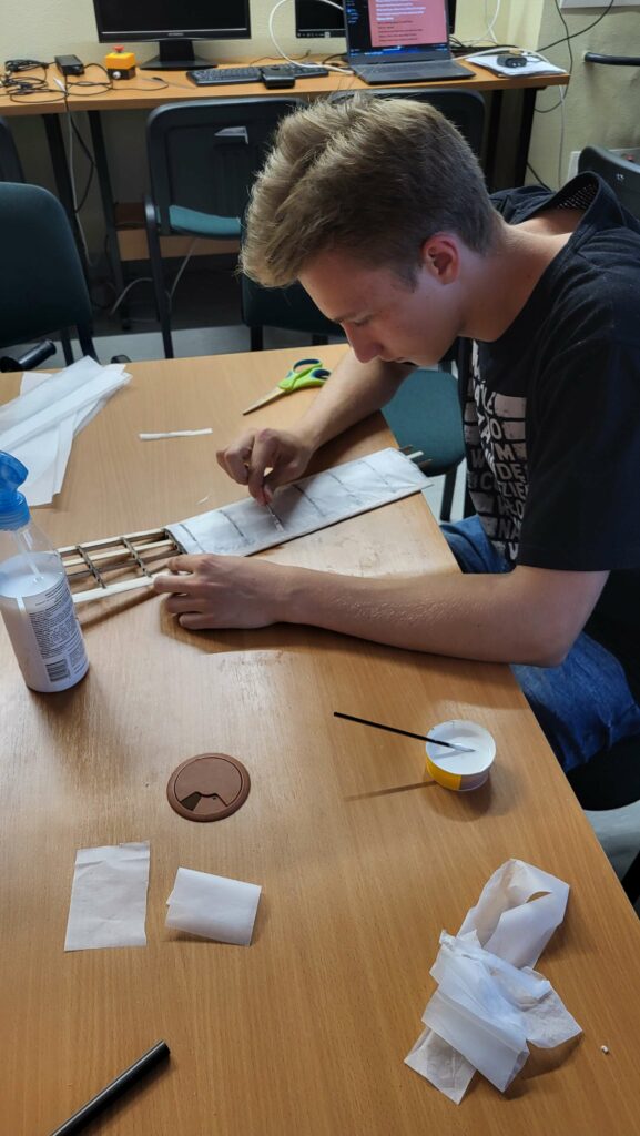
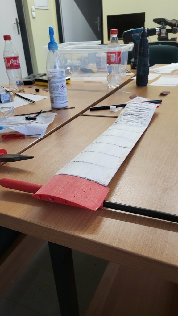
After cutting out the wing elements, we pre-sanded them and verified that the parts fit, then assembled the wings, ensured that everything was straight and started the gluing process. After waiting for the glue to dry, we got down to the sheathing. First we cut the paper to size and glued it down. After the glue dried, we used astringent varnish to smooth out the plating.
We made the stabilizers in the same way as the wings, i.e., after cutting out the parts, we sanded them with sandpaper, checked their fit, then glued them together and covered them with paper that was pulled off with varnish.
We printed the printed parts from PLA, and because of their complex geometry, they were printed with support material, so we had to remove this support material and grind the parts after printing.
Contruction: gallery
Model: gallery
