The aim of the project was to create a small, hand-launched glider for participation in the Learn&Fly competition, which is aimed at developing engineering and construction interests and skills among high school and elementary school students. It was a four-person team project undertaken by members of our club to pursue their interests in modeling and construction, while also testing their current skills in tasks related to these fields.
Project development
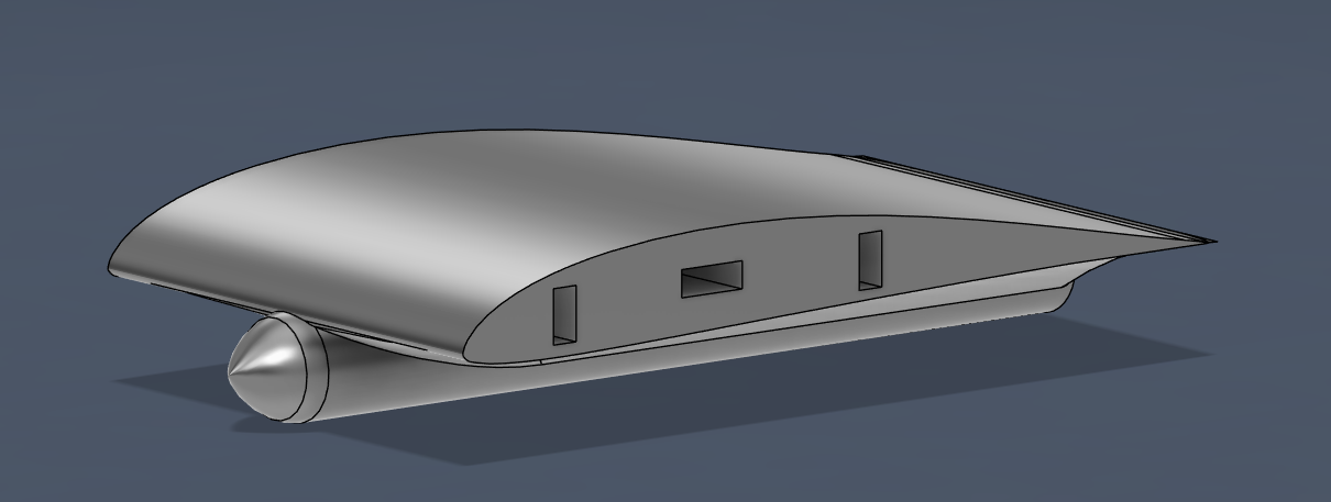
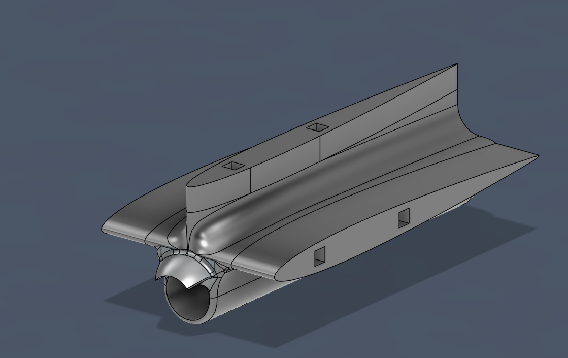
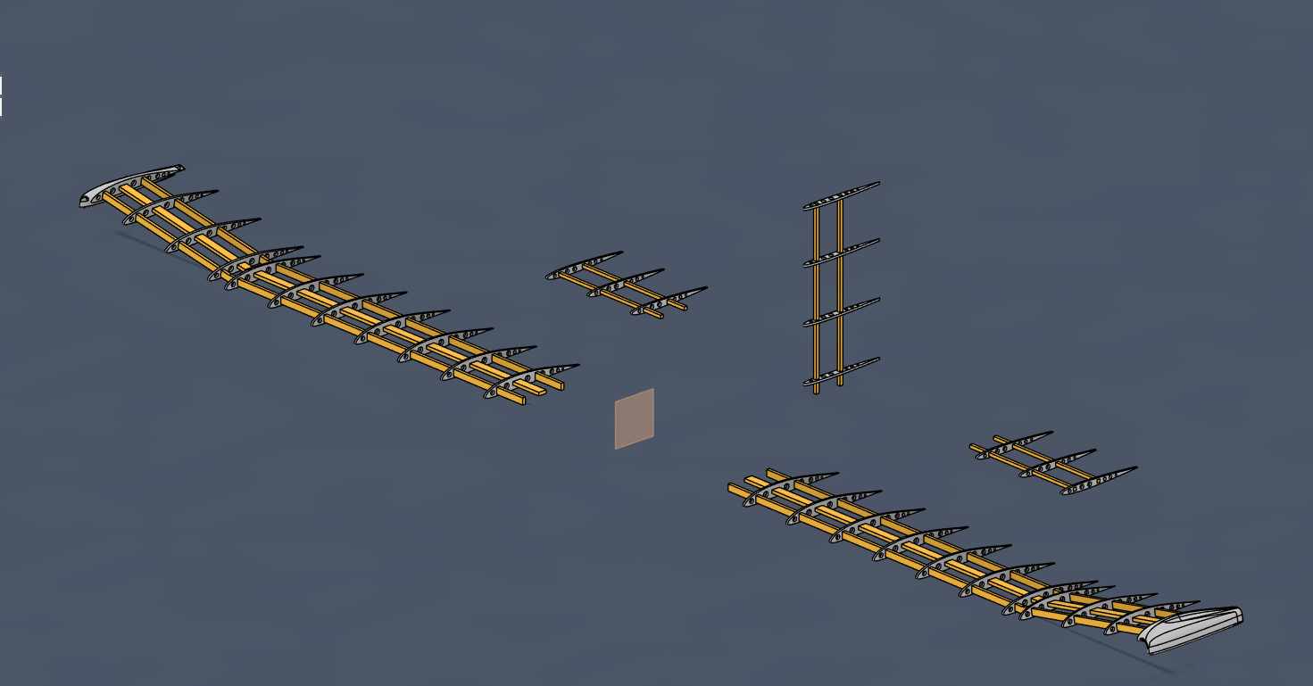
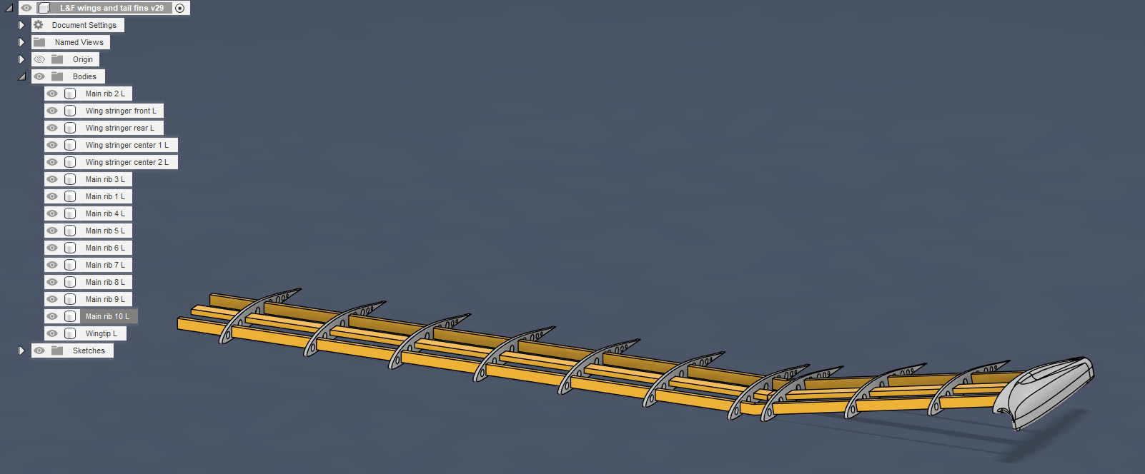
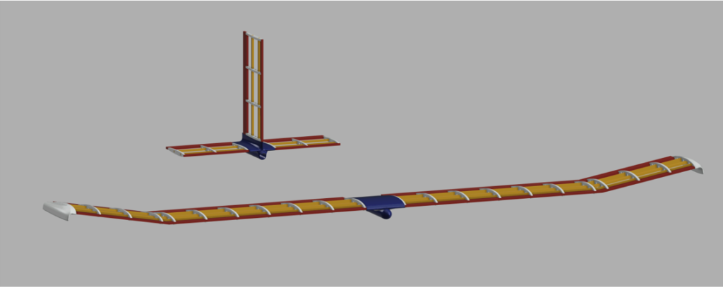
We began work on the glider by creating a 3D model. After considering several versions, we finally decided on the following glider model:
– divided into easily removable segments.
– wing and stabilizer mounts printed on a 3D printer and connected with a carbon fiber tube — printing ensures high strength, lightness, and low cost of component production.
– carbon fiber connecting fasteners — still a lightweight but durable material, forming a key structural element, the core of the entire glider.
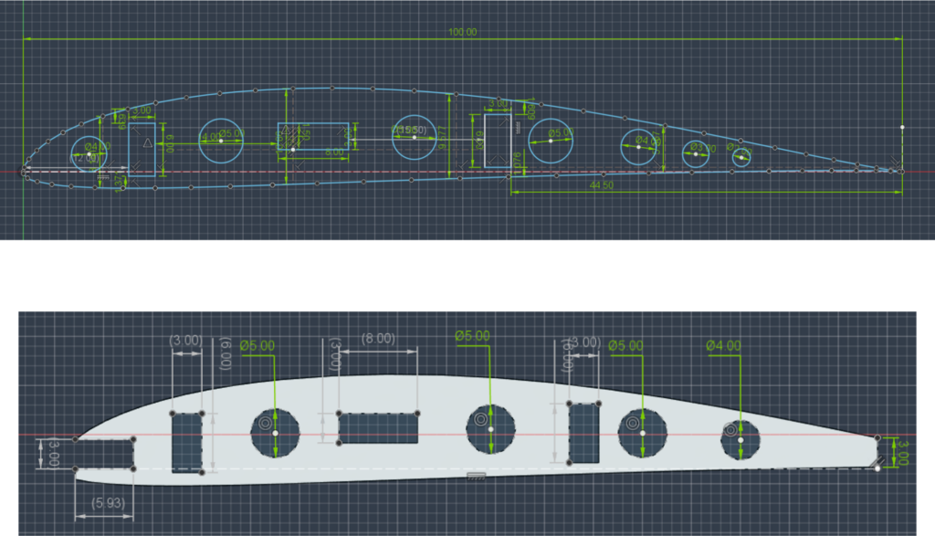
– wings made almost entirely of balsa wood, including the spars and ribs, CNC laser cut from a sheet of balsa wood. Thanks to the round holes cut in the ribs, the glider's weight is even lower.
– wing covering made of a material with a structure similar to heat-shrinkable film, ensuring low weight, relatively high strength, but most importantly, good adhesion to the wing ribs.
In addition, we want to perform an aerodynamic simulation of the designed components to ensure that the prototype in its current state will be able to achieve the desired results.
Gallery: the project

Project description
Wings
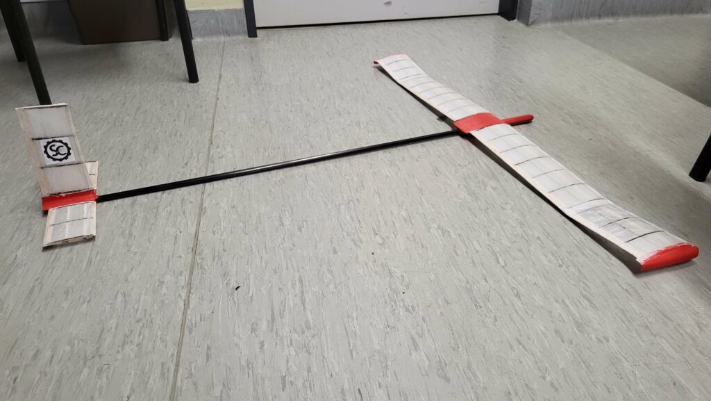
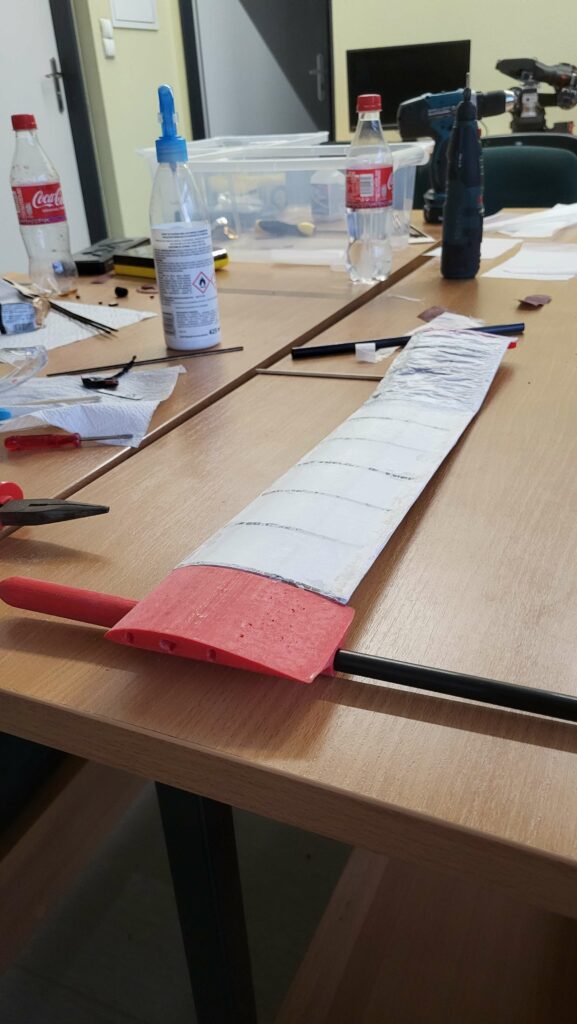
The wings have a rib-and-girder structure with an S4310 profile, bent 10 degrees upward at a distance of 31 cm from the fuselage. To protect the wings, they have a balsa wood leading edge and trailing edge. The wings have three main spars, two of which are one-piece, and one, the middle one, is divided into two parts. One wing is 488 mm long. Each wing has 10 ribs and is terminated with a winglet. These elements increase the wing's efficiency and the aircraft's horizontal stability.
Ballasts
The stabilizers also have a rib-and-girder structure, with the difference that they have only 2 girders instead of 3. They have a parachute and leading edge similar to those used in wings. The horizontal stabilizers have 3 ribs per side, while the vertical stabilizer has 4 ribs.
Wing and aileron mountings and fuselage
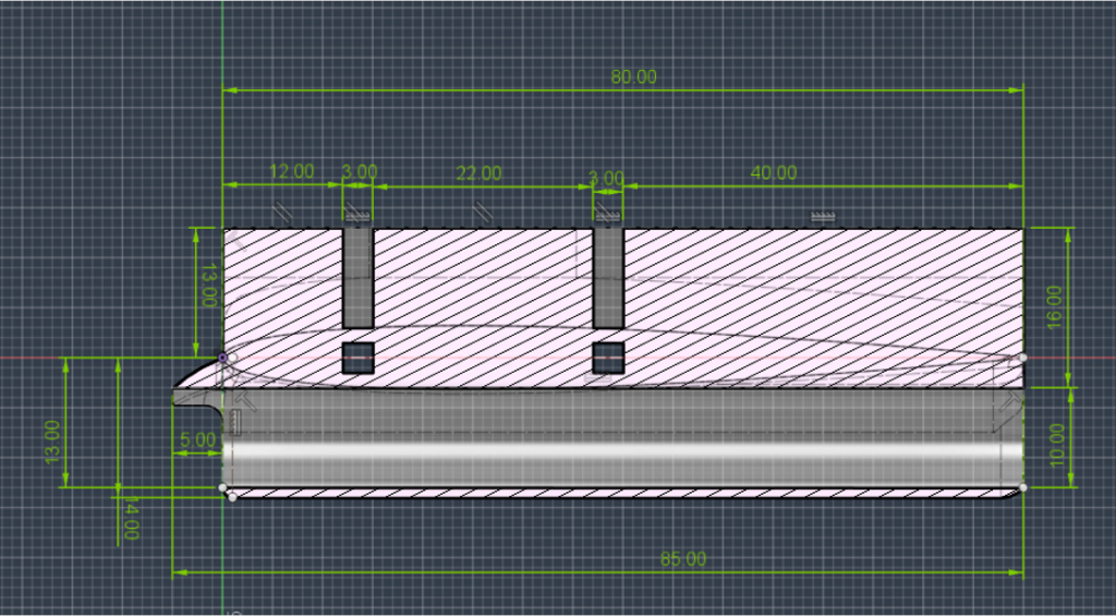
The front wing mounting was made using 3D printing, which ensures optimal strength and weight. In addition, it houses a ballast compartment and additional weights to balance the aircraft. 3D printing allows us to create complex geometries to minimize aerodynamic drag.
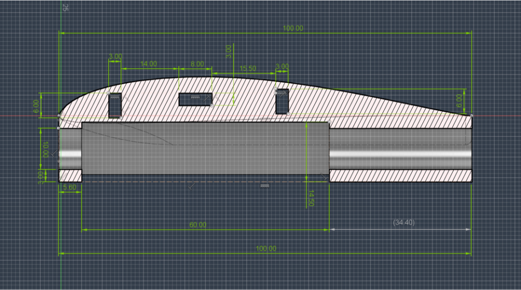
The rear element, to which the horizontal and vertical stabilizers are attached, is also manufactured using 3D printing technology.
The hull is made of carbon fiber tubes, which gives the model strength and relatively low weight. The only drawback of this solution may be excessive flexibility.
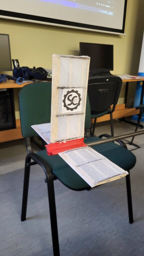
Construction and final model
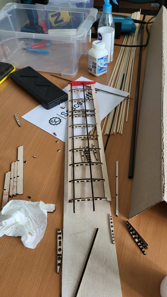
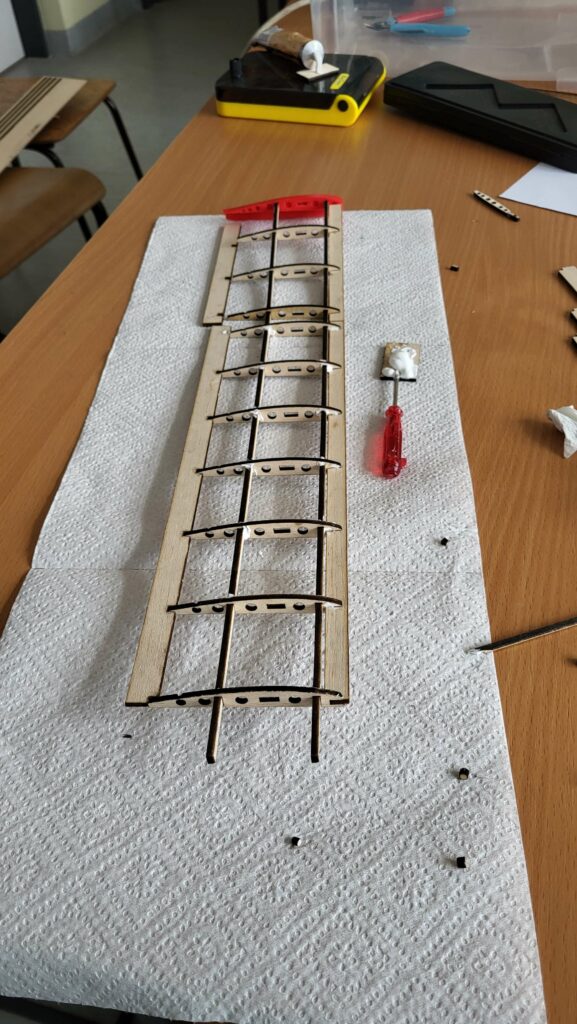
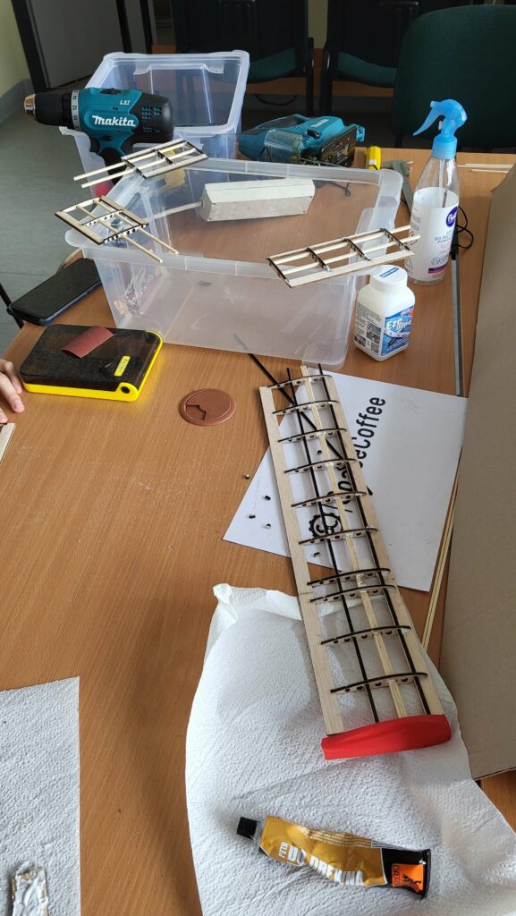
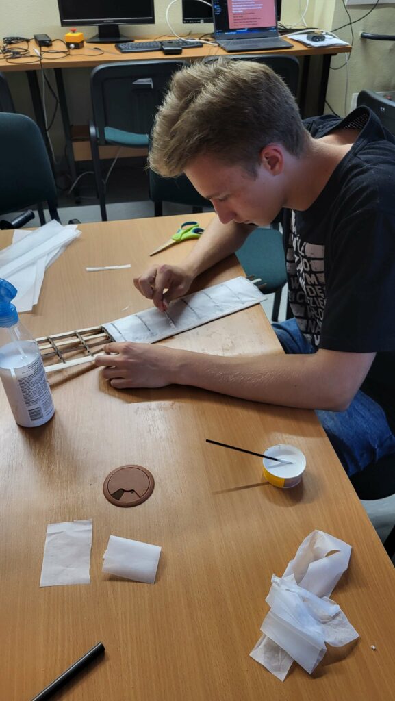
After cutting out the wing components, we sanded them down and checked that the parts fit together properly. Then we assembled the wings, made sure everything was even, and began the gluing process. After waiting for the glue to dry, we started on the covering. First, we cut the paper to the right size and glued it on. After the glue dried, we used a sanding block to smooth out the covering.
We made the stabilizers in the same way as the wings, i.e., after cutting out the parts, we sanded them with sandpaper, checked their fit, and then glued them together and covered them with paper, which was coated with varnish.
We printed the parts using PLA. Due to their complex geometry, they were printed with support material, so we had to remove this material and sand the parts.
Gallery: the assembly process
Gallery: the finished model